lunedì 27 gennaio 2014

uRPF

RPF Process

Refer to Figure 15-5 for this next illustration of RPF. Here is a simplified routing table based on the perimeter router's configuration:
199.1.1.0/24    E1
199.1.2.0/24    E0
199.1.3.0/24    E0
199.1.4.0/24    E0
199.1.5.0/24    E0
199.1.6.0/24    E0
199.1.7.0/24    E0
0.0.0.0/0       E1

Figure 15-5. Unicast RPF Example
[View full size image]
graphics/15fig05.gif


As an example, assume that the perimeter router receives a packet on E0 with an IP address of 199.1.0.5. With RPF, the router knows that this is not valid because 199.1.0.0/25 is located off E1. In this instance, the router drops the packet. Basically, the router compares the source IP address with the routes in the routing table, to make sure that the packet is received off the correct interface. The router matches source IP packets only against best paths (the ones populated in the routing table).
If an inbound ACL is applied to the interface on which RPF is enabled, the router first checks the ACL and then performs its RPF check.
NOTE
For RPF to function, CEF must be enabled on the router. This is because the router uses the Forwarding Information Base (FIB) of CEF to perform the lookup process, which is built from the router's routing table. In other words, RPF does not really look at the router's routing table; instead, it uses the CEF FIB to determine spoofing.


RPF Usage

RPF works best at the perimeter of your network. If you use it inside your network, it is used best when your routers have more specific routes. With route summarization, a spoofing attack could be in process, and it would be difficult to determine which part of the summarized route the attack is occurring from. For external threats, the more ISPs and companies use RPF, the more likely it is that spoofing attacks can be a thing of the past. However, the more point-of-presence (POP) connections that an ISP has, the more difficult it becomes to use RPF because multiple paths might exist to the source. Using RPF as close to the sources of the addresses as possible is the best solution for ISPs directly connected to their customers.
RPF is deployed best on perimeter routers in networks that have a single connection to the outside world. Of course, RPF will work in multiple-connection environments, as well as with internal routers, but it might not provide the optimum solution in detecting spoofed packets. Figure 15-6 shows an example of the problem that can occur when using RPF in a dual-connection network. In this example, the perimeter router uses interface S0 to send traffic to the remote site. However, using BGP, the Internet has determined that the best path to return the traffic to the network on the left is to send this through S1 on the perimeter router. This creates a problem on the perimeter router with RPF because using its routing table, the router expects this traffic to come through S0. In this instance, the router would drop the returning traffic.
Figure 15-6. RPF and Dual-Connection Problems
[View full size image]
graphics/15fig06.gif

One exception to using RPF for single connections is to use dialup access on an access server. One of the main sources of spoofing attacks is dialup access. By using RPF on your access servers, you can limit your exposure to this method of spoofing attack.
An alternative to RPF is to use ACLs. However, the main problem of ACLs are their performance and day-to-day maintenance. RPF, on the other hand, relies on information from the routing table, which can be built statically or dynamically. With CEF handling the process, you are not taking a performance hit.


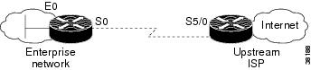
In this example, Unicast RPF is applied at interface S0 on the enterprise router for protection from malformed packets arriving from the Internet. Unicast RPF is also applied at interface S5/0 on the ISP router for protection from malformed packets arriving from the enterprise network.
Figure 40 Enterprise Network Using Unicast RPF for Ingress Filtering 


Using the topography in , a typical configuration (assuming that CEF is turned on) on the ISP router would be as follows:
ip cef
interface loopback 0
  description Loopback interface on Gateway Router 2
  ip address 192.168.3.1 255.255.255.255
  no ip redirects
  no ip directed-broadcast
  no ip proxy-arp
interface Serial 5/0
  description 128K HDLC link to ExampleCorp WT50314E  R5-0
  bandwidth 128
  ip unnumbered loopback 0
  ip verify unicast reverse-path
  no ip redirects
  no ip directed-broadcast
  no ip proxy-arp
ip route 192.168.10.0 255.255.252.0 Serial 5/0

The gateway router configuration of the enterprise network (assuming that CEF is turned on) would look similar to the following:
 
ip cef
interface Ethernet 0
 description ExampleCorp LAN
 ip address 192.168.10.1 255.255.252.0
 no ip redirects
 no ip directed-broadcast
 no ip proxy-arp
interface Serial 0
 description 128K HDLC link to ExampleCorp Internet Inc WT50314E  C0
 bandwidth 128
 ip unnumbered ethernet 0
 ip verify unicast reverse-path
 no ip redirects
 no ip directed-broadcast
 no ip proxy-arp
ip route 0.0.0.0 0.0.0.0 Serial 0

Notice that Unicast RPF works with a single default route. There are no additional routes or routing protocols. Network 192.168.10.0/22 is a connected network. Hence, packets coming from the Internet with a source address in the range 192.168.10.0/22 will be dropped by Unicast RPF.

martedì 21 gennaio 2014

MULTICAST : SHARED TREE vs SOURCE TREE

Rendezvous Points

When configuring PIM-SM on a network, at least one router must be designated as a rendezvous point (RP). The RP could be configured manually, or dynamically through Cisco's Auto-RP or PIMv2's Bootstrap Router (BSR) method. Regardless of which method is used, an RP performs a critical function: it establishes a common reference point from which multicast trees are grown.

Consider the following topology:
topology.png
PIM-SM is enabled on all router interfaces, and R2's loopback address of 2.2.2.2 has been statically configured as the RP on all routers in the network, including R2 itself, with the ip pim rp-address command.
 
R2(config)# ip pim rp-address 2.2.2.2

With an RP established, we can observe what happens when a source begins to transmit multicast traffic.


Source Trees

Assume a multicast server connected to R1 begins sending multicast traffic for group 239.1.2.3. When R1 receives this traffic, it recognizes it as destined for a multicast group because the destination IP address (239.1.2.3) resides in the 224.0.0.0/4 range. R1 automatically installs two routes in its multicast routing table:
 
R1# show ip mroute 239.1.2.3
IP Multicast Routing Table
Flags: D - Dense, S - Sparse, B - Bidir Group, s - SSM Group, C - Connected,
   L - Local, P - Pruned, R - RP-bit set, F - Register flag,
   T - SPT-bit set, J - Join SPT, M - MSDP created entry,
   X - Proxy Join Timer Running, A - Candidate for MSDP Advertisement,
   U - URD, I - Received Source Specific Host Report,
   Z - Multicast Tunnel, z - MDT-data group sender,
   Y - Joined MDT-data group, y - Sending to MDT-data group
Outgoing interface flags: H - Hardware switched, A - Assert winner
 Timers: Uptime/Expires
 Interface state: Interface, Next-Hop or VCD, State/Mode

(*, 239.1.2.3), 00:00:13/stopped, RP 2.2.2.2, flags: SPF    --> SHARED TREE
  Incoming interface: FastEthernet0/0, RPF nbr 10.0.12.2
  Outgoing interface list: Null

(192.168.1.100, 239.1.2.3), 00:00:13/00:02:58, flags: PFT   --> SOURCE TREE
  Incoming interface: FastEthernet1/0, RPF nbr 0.0.0.0, Registering
  Outgoing interface list: Null
 
The (*, 239.1.2.3) route represents the a shared tree rooted at the RP (notice the incoming interface listed as FastEthernet0/0, from R2). This tree hasn't actually been built yet; think of the route as a placeholder. The (192.168.1.100, 239.1.2.3) route represents the source tree, rooted at the multicast source (from FastEthernet1/0).
R1 does not immediately begin forwarding the multicast traffic; note that the outgoing interface list (OIL) for both routes is null. Instead, R1 begins encapsulating multicast packets from the source into PIM register messages and forwards them toward the RP. Note that the register messages are addressed to the group (239.1.2.3), not to the RP itself.
When the RP receives the first register message, it creates its own entries for the two trees:
 
R2# show ip mroute 239.1.2.3

(*, 239.1.2.3), 00:03:56/stopped, RP 2.2.2.2, flags: SP   --> SHARED TREE
  Incoming interface: Null, RPF nbr 0.0.0.0
  Outgoing interface list: Null

(192.168.1.100, 239.1.2.3), 00:00:05/00:02:54, flags: P   --> SOURCE TREE
  Incoming interface: FastEthernet0/0, RPF nbr 10.0.12.1
  Outgoing interface list: Null
 
Notice that the source tree is listed as incoming from R1, while the shared tree has no incoming interfaces, as it isn't built from the RP until at least one member has joined the group. Maintaining a source tree from the source to the RP ensures the RP knows the address of the multicast source(s) for the group.
source_tree.png

After creating the two routes in its multicast routing table, the RP sends a register stop message to R1, informing it to stop sending register messages. The delay between register and register stop messages is typically only a fraction of a second.
Routes for both trees will remain in the tables of both routers as long as multicast traffic is being sent to the group. At this point, neither R3 nor R4 have any knowledge of the 239.1.2.3 group:
 
R3# show ip mroute 239.1.2.3
Group 239.1.2.3 not found

Shared Trees

Enter a group member on R3. The multicast client indicates to R3 it wants to receive traffic for the 239.1.2.3 group via IGMP. R3 annotates the IGMP join in its multicast routing table and sends a PIM join request for the group to the RP (R2). The RP receives the join request from R3, and adds FastEthernet0/1 (to R3) in the outgoing interface lists for both mroutes:
 
R2# show ip mroute 239.1.2.3

(*, 239.1.2.3), 00:00:30/00:03:17, RP 2.2.2.2, flags: S  --> SHARED TREE
  Incoming interface: Null, RPF nbr 0.0.0.0
  Outgoing interface list:
FastEthernet0/1, Forward/Sparse, 00:00:12/00:03:17

(192.168.1.100, 239.1.2.3), 00:00:30/00:03:23, flags: T  --> SOURCE TREE
  Incoming interface: FastEthernet0/0, RPF nbr 10.0.12.1
  Outgoing interface list:
FastEthernet0/1, Forward/Sparse, 00:00:12/00:03:17

In this manner, the source and shared trees are joined. However, because the RP didn't previously have any outgoing interfaces for either tree, it issues its own join request up the source tree to R1, requesting that multicast traffic for the group be forwarded to the RP.
Upon receiving the RP's join request on the source tree, R1 removes the prune (P) flag from its (192.168.1.100, 239.1.2.3) mroute and adds FastEthernet0/0 (to R2) as an outgoing interface:
 
R1# show ip mroute 239.1.2.3

(*, 239.1.2.3), 00:00:33/stopped, RP 2.2.2.2, flags: SPF  --> SHARED TREE
  Incoming interface: FastEthernet0/0, RPF nbr 10.0.12.2
  Outgoing interface list: Null

(192.168.1.100, 239.1.2.3), 00:00:33/00:03:20, flags: FT  --> SOURCE TREE
  Incoming interface: FastEthernet1/0, RPF nbr 0.0.0.0
  Outgoing interface list:
FastEthernet0/0, Forward/Sparse, 00:00:15/00:03:14
 
Multicast traffic is now flowing from the source on R1 to the group member on R3.

shared_tree.png

Compare the table of R1 (on the source tree) to that of R3 (on the shared tree):
 
R3# show ip mroute 239.1.2.3

(*, 239.1.2.3), 00:00:22/00:02:59, RP 2.2.2.2, flags: SCL  --> SHARED TREE
  Incoming interface: FastEthernet0/1, RPF nbr 10.0.23.2
  Outgoing interface list:
FastEthernet1/0, Forward/Sparse, 00:00:22/00:02:55

Notice that R3 has only a single route, (*, 239.1.2.3), for the shared tree rooted at the RP; it has no knowledge of the source tree between R1 and R2.
When additional members join the multicast group, the shared tree is simply extended through additional join requests between PIM routers:

shared_tree2.png
R4# show ip mroute 239.1.2.3

(*, 239.1.2.3), 00:00:08/00:02:59, RP 2.2.2.2, flags: SCL
  Incoming interface: FastEthernet0/0, RPF nbr 10.0.34.3
  Outgoing interface list:
FastEthernet1/0, Forward/Sparse, 00:00:08/00:02:55

One final note: after Cisco PIM-SM routers have determined the source of multicast traffic for a group, they will by default switch over to a source tree in order to more efficiently forward traffic. For example, assuming all links have an equal cost, multicast traffic has a more favorable route to R4 via the direct link from R1. PIM is able to detect this by inspecting the unicast routing table, and R4 will switch over to a source tree by sending a PIM join request to R1:

new_source_tree.png
R4# show ip mroute 239.1.2.3

(*, 239.1.2.3), 00:00:22/00:02:38, RP 2.2.2.2, flags: SJCL
  Incoming interface: FastEthernet0/0, RPF nbr 10.0.34.3
  Outgoing interface list:
FastEthernet1/0, Forward/Sparse, 00:00:22/00:02:37

(192.168.1.100, 239.1.2.3), 00:00:21/00:02:58, flags: LJT
  Incoming interface: FastEthernet0/1, RPF nbr 10.0.14.1
  Outgoing interface list:
FastEthernet1/0, Forward/Sparse, 00:00:21/00:02:38
 
This behavior can be disabled with the ip pim spt-threshold infinity command.

sabato 18 gennaio 2014

IPV6 multicast Boundary with or without filter-autorp

So what is the use of "filter-autorp" option in the "ip multicast boundary" command? Let's explore it with an example:
Here R3 is the multicast source and R2 is the client. R1 is serving as RP the for multicast groups 226.0.0.0/8, 228.0.0.0/8, and 232.0.0.0/5. R1 ia also the mapping agent. Let's check the relevant configuration on those routers:
Rack1R3
ip multicast-routing
!
interface Serial1/2
 ip address 180.1.13.3 255.255.255.0
 ip pim sparse-mode
!
ip pim autorp listener

Rack1R1
ip multicast-routing
!
interface FastEthernet0/0
 ip address 180.1.12.1 255.255.255.0
 ip pim sparse-mode
!
interface Serial0/1
 ip address 180.1.13.1 255.255.255.0
 ip pim sparse-mode
!
ip pim autorp listener
ip pim send-rp-announce FastEthernet0/0 scope 16 group-list RP_GROUPS interval 5
ip pim send-rp-discovery FastEthernet0/0 scope 16 interval 5
!
ip access-list standard RP_GROUPS
 permit 232.0.0.0 7.255.255.255
 permit 226.0.0.0 0.255.255.255
 permit 228.0.0.0 0.255.255.255

Rack1R2
ip multicast-routing
!
interface Loopback0
 ip address 2.2.2.2 255.255.255.255
 ip pim sparse-mode
!
interface FastEthernet0/0
 ip address 180.1.12.2 255.255.255.0
 ip pim sparse-mode
!
ip pim autorp listener

Rack1R2#show ip pim rp mapping
PIM Group-to-RP Mappings
Group(s) 226.0.0.0/8
  RP 180.1.12.1 (?), v2v1
    Info source: 180.1.12.1 (?), elected via Auto-RP
         Uptime: 00:09:43, expires: 00:00:12
Group(s) 228.0.0.0/8
  RP 180.1.12.1 (?), v2v1
    Info source: 180.1.12.1 (?), elected via Auto-RP
         Uptime: 00:09:43, expires: 00:00:12
Group(s) 232.0.0.0/5
  RP 180.1.12.1 (?), v2v1
    Info source: 180.1.12.1 (?), elected via Auto-RP
         Uptime: 00:09:43, expires: 00:00:12
So from the above output we can see that R2 is learning auto-rp information from R1 (mapping-agent). Now we will simulate a multicast client on R2's loopback interface for one of the auto-rp group.
Rack1R2(config-if)#int lo0
Rack1R2(config-if)#ip add 2.2.2.2 255.255.255.255
Rack1R2(config-if)#ip pim sparse-mode
Rack1R2(config-if)#ip igmp join-group 228.0.0.1
Rack1R3#ping 228.0.0.1
Type escape sequence to abort.
Sending 1, 100-byte ICMP Echos to 228.0.0.1, timeout is 2 seconds:
Reply to request 0 from 180.1.12.2, 32 ms   
So we can see that multicast traffic for group 228.0.0.1 flowing from the source (R3) to the client (R2). Now we will apply "ip multicast boundary" command on R2 without "filter-autorp" option:
Rack1R2(config)#ip access-list standard FILTER_MULTICAST
Rack1R2(config-std-nacl)#deny 228.0.0.0 0.255.255.255
Rack1R2(config-std-nacl)#permit any
Rack1R2(config-std-nacl)#int fa0/0
Rack1R2(config-if)#ip multicast boundary FILTER_MULTICAST
Rack1R3#ping 228.0.0.1 rep 3
Type escape sequence to abort.
Sending 3, 100-byte ICMP Echos to 228.0.0.1, timeout is 2 seconds:
...
Rack1R2(config-if)#do sh access-list FILTER_MULTICAST
Standard IP access list FILTER_MULTICAST
    10 deny   228.0.0.0, wildcard bits 0.255.255.255 (3 matches)
    20 permit any (15 matches)
Rack1R2(config-if)#do show ip pim rp mapping
PIM Group-to-RP Mappings
Group(s) 226.0.0.0/8
  RP 180.1.12.1 (?), v2v1
    Info source: 180.1.12.1 (?), elected via Auto-RP
         Uptime: 01:17:04, expires: 00:00:13
Group(s) 228.0.0.0/8  RP 180.1.12.1 (?), v2v1
    Info source: 180.1.12.1 (?), elected via Auto-RP
         Uptime: 00:15:42, expires: 00:00:13
Group(s) 232.0.0.0/5
  RP 180.1.12.1 (?), v2v1
    Info source: 180.1.12.1 (?), elected via Auto-RP
         Uptime: 01:17:04, expires: 00:00:13
From the above example we can see that even though R2 blocked 228.0.0.0/8 group traffic, it is still learning auto-rp information for 228.0.0.0/8. Now we will add "filter-autorp" option and will see the differences:
Rack1R2(config-std-nacl)#int fa0/0
Rack1R2(config-if)#ip multicast boundary FILTER_MULTICAST filter-autorp
Rack1R2(config-if)#do show ip pim rp mapping
PIM Group-to-RP Mappings
Group(s) 226.0.0.0/8
  RP 180.1.12.1 (?), v2v1
    Info source: 180.1.12.1 (?), elected via Auto-RP
         Uptime: 00:11:34, expires: 00:00:11
Group(s) 232.0.0.0/5
  RP 180.1.12.1 (?), v2v1
    Info source: 180.1.12.1 (?), elected via Auto-RP
         Uptime: 00:11:34, expires: 00:00:11
So now R2 is not only blocking the 228.0.0.0/8 group but also blocking the auto-rp information for that group.
Here comes a gotcha:
Rack1R2(config)#interface Loopback0
Rack1R2(config-if)#ip igmp join-group 234.0.0.1
Rack1R3#ping 234.0.0.1
Type escape sequence to abort.
Sending 1, 100-byte ICMP Echos to 234.0.0.1, timeout is 2 seconds:
Reply to request 0 from 180.1.12.2, 36 ms
Rack1R2(config)#do sh access-list FILTER_MULTICAST
Standard IP access list FILTER_MULTICAST
    10 deny   228.0.0.0, wildcard bits 0.255.255.255 (19 matches)
    20 permit any (394 matches)
Rack1R2(config)#ip access-list standard FILTER_MULTICAST
Rack1R2(config-std-nacl)#15 deny 236.0.0.0 0.255.255.255
*May 08 11:17:12.655: %AUTORP-4-OVERLAP: AutoRP Discovery packet, group 232.0.0.0 with mask 248.0.0.0 removed because of multicast boundary for 236.0.0.0 with mask 255.0.0.0
Rack1R2(config-std-nacl)#do sh ip pim rp mapp
PIM Group-to-RP Mappings
Group(s) 226.0.0.0/8
  RP 180.1.12.1 (?), v2v1
    Info source: 180.1.12.1 (?), elected via Auto-RP
         Uptime: 01:36:12, expires: 00:00:13
Rack1R3#ping 234.0.0.1 rep 3
Type escape sequence to abort.
Sending 3, 100-byte ICMP Echos to 234.0.0.1, timeout is 2 seconds:
...
From the above output we can see that as soon as we blocked the 236.0.0.0/8 group, the entire group range 232.0.0.0/5 was filtered and removed from the Auto-RP message. That's why R2 has no auto-rp information for group 234.0.0.1, a subset of 232.0.0.0/5. We can fix this by running sparse-dense mode on the interfaces so that traffic for group 234.0.0.1 will be able to use dense-mode. Another option is to configure RP R1 to announce 234.0.0.0/8 and 236.0.0.0/8 group individually instead of advertising the group range of 232.0.0.0/5.
So the key point is ... With auto-rp configured, RP by default announces itself as the RP for all the multicast groups (224.0.0.0/4). Now if we filter any specific group using "filter-autorp" keyword, it will filter auto-rp information for all the multicast groups unless RP advertises specific multicast groups rather than advertising default 224.0.0.0/4.